
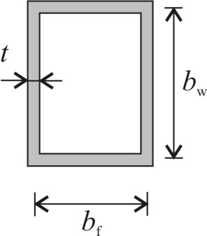
 A box section beam has the outer dimensions 150 × 250 mm. Walls are isotropic, their thickness is 5 mm, and their stiffness is: D = 2.4 kNm. The beam is subjected to an axial normal force, P. Give the maximum allowed value of P based on local buckling.
Solve Problem
Buckling load of the cross section, Pcr[kN]=Solve
Do you need help?
Steps
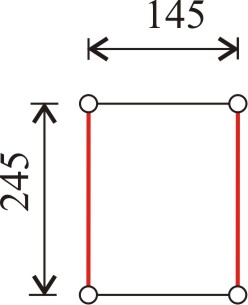
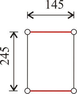
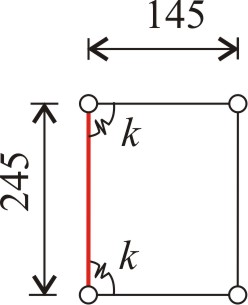
Step 1. Determine the buckling loads of the flange and the web assuming hinged supports Web buckling is relevant. Step 2. Determine the spring constant. Step 3. Determine the buckling load of the rotationally restrained web. Step 4. Give the critical force of the total cross section. The critical load, P acting on the cross section which causes the buckling of the web is Step by stepShow buckling loads with hinged supports

Show spring constant
Show buckling load of the web
Show critical load
Results
First hinged connections are assumed. The buckling loads of the flange and the web are Web buckling is relevant. Now we calculate the buckling load of the rotationally restrained web. The spring constant represents the restraining effect of flanges must be determined. The buckling load of the rotationally restrained web is The critical force of the total cross section results in:Worked out solution