
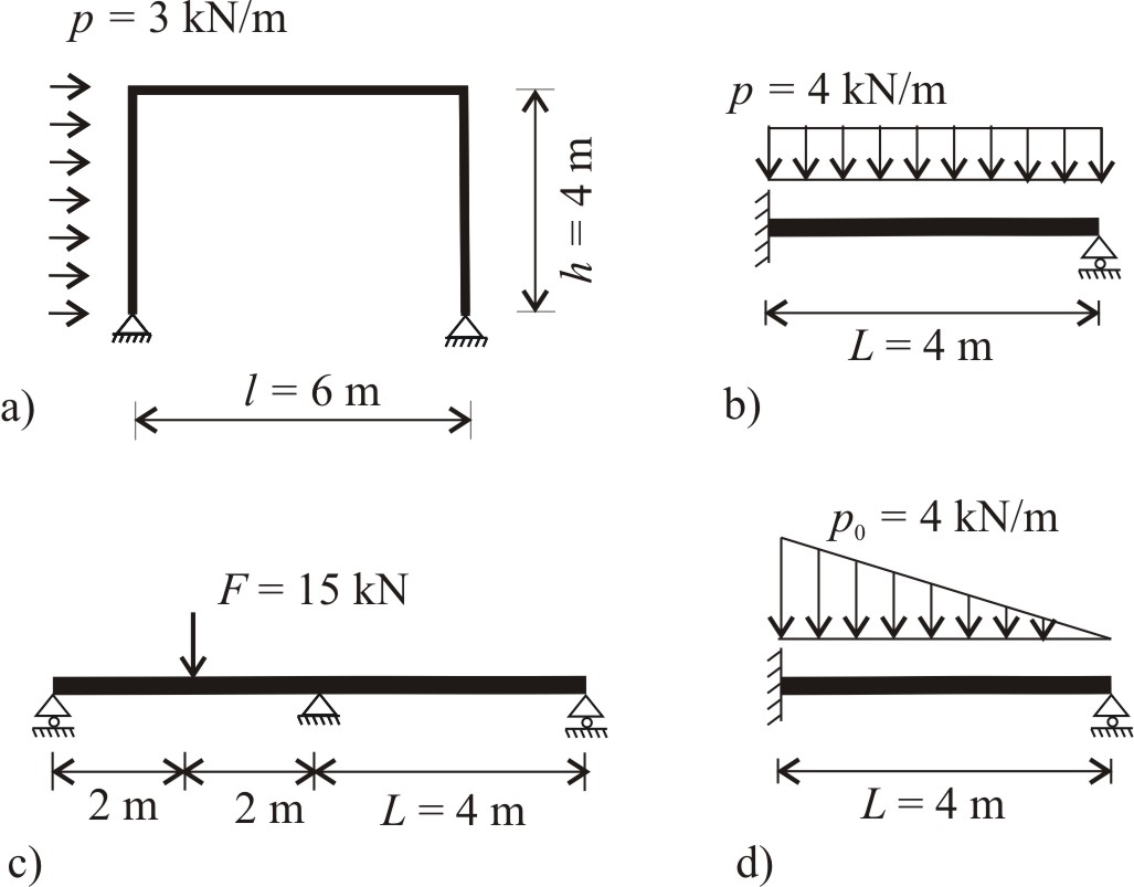
Determine the bending moment diagrams of the statically indeterminate elastic structures given in the Figures a)-d) with the aid of the force method. Bending stiffness, EI of the girders are uniform, compressibility of the elements is neglected.
Solve Problem
Problem a) Maximum moment, Mmax [kNm]= Problem b) Maximum moment, Mmax [kNm]= Problem c) Maximum moment, Mmax [kNm]= Problem d) Maximum moment, Mmax [kNm]=Solve
Do you need help?
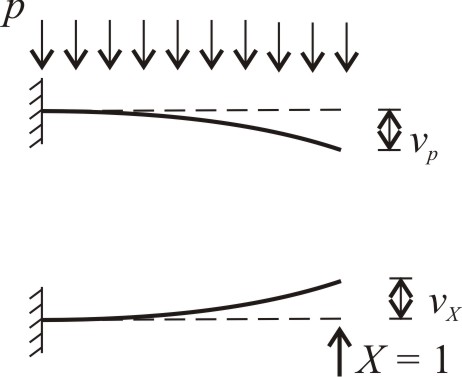
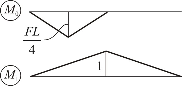
Steps Problem a) Step 1. Define a primary structure. Choose the redundant. The horizontal support of the right hinge is removed to obtain a statically determined primary structure. The redundant is a horizontal force, X acting at the right support. Step 2. Calculate the displacements at the right support from the original load and from the redundant. The displacements of the frame subjected to uniformly distributed and concentrated loads are derived in Problem 6.9. The results are: Step 3. Determine the redundant from the compatibility condition. The displacement at the right support must be zero Step 4. Apply superposition to give the moment diagram of the statically indeterminate structure. The maximum moment is Problem b) Step 1. Define a primary structure. Choose the redundant. Removing the right support the primary structure is chosen to be a cantilever. The redundant is a vertical force, X acting at the free end of the beam. Step 2. Calculate the deflection at the beam end from the original load and from the redundant. Step 3. Determine the redundant from the compatibility condition. The displacement at the beam end support must be zero Step 4. Apply superposition to give the moment diagram of the statically indeterminate structure. The maximum moment arises at the built-in support Problem c) Step 1. Define a primary structure. Choose the redundant. A hinge is introduced above the middle support, thus the primary structure becomes two simply supported girders. The redundant is a moment couple, X shown in the Figure. Step 2. Calculate the relative rotation above the middle support from the original load and from the redundant. The relative rotations are calculated by Castigliano’s theorem: Step 3. Determine the redundant from the compatibility condition. The relative rotation above the middle support must be zero: Step 4. Apply superposition to give the moment diagram of the statically indeterminate structure. The maximum negative moment above the support is The maximum positive moment below the force is Problem d) Step 1. Define a primary structure. Choose the redundant. The primary structure and the redundant is chosen similarly as in Problem a). On the cantilever a linearly distributed load, and a concentrated end force act. Step 2. Calculate the deflection at the beam end from the original load and from the redundant. End deflection of a cantilever subjected to linearly distributed load is derived in Problem 6.7 a), end rotation from the redundant is equivalent to that of Problem b): Step 3. Determine the redundant from the compatibility condition. The deflection at the beam end must be zero Step 4. Apply superposition to give the moment diagram of the statically indeterminate structure. The maximum moment arises at the built-in supportStep by step
Show steps of Solution a)Check figure
Check displacements
Check redundantsCheck result
Show steps of Solution b)Check figure
Check deflections
Check redundantsCheck result
Show steps of Solution c)Check figure

Check rotations
Check redundantsCheck result
Show steps of Solution d)Check figure
Check deflectionsCheck redundantsCheck result
Results Problem a) The horizontal support of the right hinge is removed to obtain a statically determined primary structure. The redundant is a horizontal force, X acting at the right support. The displacements of the frame subjected to uniformly distributed and concentrated loads are derived in Problem 6.9. The results are: The redundant is determined from the compatibility condition. The displacement at the right support must be zero: Superposition is applied to give the moment diagram of the statically indeterminate structure: The maximum moment is Problem b) Removing the right support the primary structure is chosen to be a cantilever. The redundant is a vertical force, X acting at the free end of the beam. The deflection at the beam end from the original load and from the redundant is calculated. The redundant is determined from the compatibility condition. Superposition is applied to give the moment diagram of the statically indeterminate structure: The maximum moment arises at the built-in support Problem c) A hinge is introduced above the middle support, thus the primary structure becomes two simply supported girders. The redundant is a moment couple, X shown in the Figure. The relative rotation above the middle support from the original load and from the redundant is calculated by Castigliano’s theorem: The redundant is determined from the compatibility condition. Superposition is applied to give the moment diagram of the statically indeterminate structure. The maximum negative moment above the support is The maximum positive moment below the force is Problem d) The primary structure and the redundant is chosen similarly as in Problem b). On the cantilever a linearly distributed load, and a concentrated end force act. The deflection at the beam end from the original load and from the redundant is calculated. End deflection of a cantilever subjected to linearly distributed load is derived in Problem 6.7 a), end rotation from the redundant is equivalent to that of Problem b): The redundant is determined from the compatibility condition. The deflection at the beam end must be zero Superposition is applied to give the moment diagram of the statically indeterminate structure. The maximum moment arises at the built-in supportWorked out solution
Show Solution a)Show Solution b)
The displacement at the beam end support must be zero:Show Solution c)
The relative rotation above the middle support must be zero:Show Solution d)