
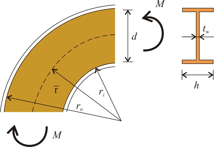
 A curved I-beam is subjected to uniform bending moment, M. Central distance between the flanges, d and the thickness of the web tw are
given. (The difference between d and the height of the beam is neglected.) Three radii are examined: . Suppose thin web, so the normal tress, σφ in the web is negligible. Determine and sketch stress, σr in the web.
a) d = 0.4 m, tw = 2 mm, M = 120 kNm,
b) d = 0.3 m, tw = 4 mm, M = 100 kNm,
c) d = 0.4 m, tw = 3 mm, M = 140 kNm.

Solve Problem
Check the results for the first set of initial data. Problem a) Stress at the top of the web, Stress at the bottom of the web, Sketch radial stresses of the web. Calculate results for all the other set of initial data.SolveCheck figure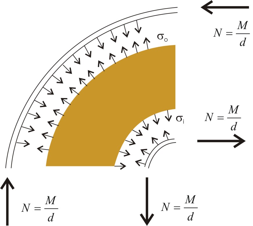
Check table
Problem a)
Problem b)
Problem c)
2
5
10
2
5
10
2
5
10
d [m]
0.4
0.3
0.4
tw [mm]
2
4
3
M [kNm]
120
100
140
[m]
0.8
2
4
0.6
1.5
3
0.8
2
4
ro [m]
1
2.2
4.2
0.75
1.65
3.15
1
2.2
4.2
r1[m]
0.6
1.8
3.8
0.45
1.35
2.85
0.6
1.8
3.8
N [kN]
300
333.33
350
σo [N/mm2]
150
68.18
35.71
111.11
50.51
26.45
116.67
53.03
27.78
σi [N/mm2]
250
83.33
39.47
185.18
61.73
29.24
194.44
64.82
30.70
Do you need help?
Steps
Solution for the first set of initial data of Problem a) is presented. Step 1. Express the radii of the curvature at the edges of the beam from the initial data. Step 2. Determine the approximate normal force in the flanges. We assume that moment is carried only by the flanges, normal stresses in the web are neglected: Step 3. Calculate the radial stresses in the web which arise from the tension and compression of curved flanges. Apply the pressure vessel formula: Step 4. Sketch stresses. Step 5. Calculate results for all the other set of initial data.Step by stepCheck curvaturesCheck normal forceCheck top radial stress
Check bottom radial stressCheck figureCheck table
Problem a)
Problem b)
Problem c)
2
5
10
2
5
10
2
5
10
d [m]
0.4
0.3
0.4
tw [mm]
2
4
3
M [kNm]
120
100
140
[m]
0.8
2
4
0.6
1.5
3
0.8
2
4
ro [m]
1
2.2
4.2
0.75
1.65
3.15
1
2.2
4.2
r1[m]
0.6
1.8
3.8
0.45
1.35
2.85
0.6
1.8
3.8
N [kN]
300
333.33
350
σo [N/mm2]
150
68.18
35.71
111.11
50.51
26.45
116.67
53.03
27.78
σi [N/mm2]
250
83.33
39.47
185.18
61.73
29.24
194.44
64.82
30.70
Results
Solution for the first set of initial data of Problem a) is presented. The radii of the curvature at the edges of the beam are expressed from the initial data. We assume that moment is carried only by the flanges, normal stresses in the web are neglected. The approximate normal force in the flanges is The radial stresses in the web arise from the tension and compression of curved flanges. Applying the pressure vessel formula the top and bottom radial stresses are Results for the other sets of initial data areWorked out solutions
Problem a)
Problem b)
Problem c)
2
5
10
2
5
10
2
5
10
d [m]
0.4
0.3
0.4
tw [mm]
2
4
3
M [kNm]
120
100
140
[m]
0.8
2
4
0.6
1.5
3
0.8
2
4
ro [m]
1
2.2
4.2
0.75
1.65
3.15
1
2.2
4.2
r1[m]
0.6
1.8
3.8
0.45
1.35
2.85
0.6
1.8
3.8
N [kN]
300
333.33
350
σo [N/mm2]
150
68.18
35.71
111.11
50.51
26.45
116.67
53.03
27.78
σi [N/mm2]
250
83.33
39.47
185.18
61.73
29.24
194.44
64.82
30.70