
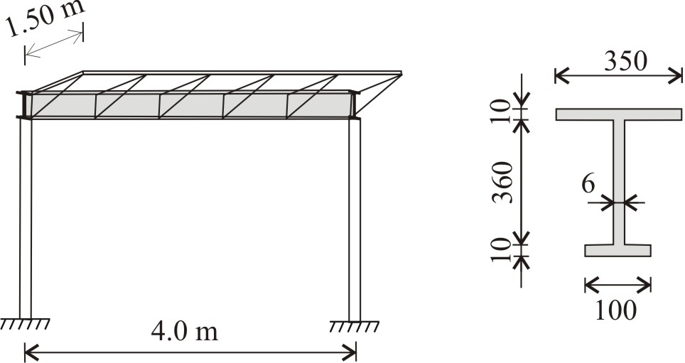
The main girder of a bus stop booth is given in the Figure. The thin walled steel beam has fork supports. Determine the torque in the beam (assume uniform distribution), calculate the stiffnesses of the cross section. Write the differential equation describing the equilibrium of the beam, give the boundary conditions. The vertical load on the roof is uniformly distributed p = 4.0 kN/m2 (contains the snow load and the self-weights of the glass roof and of the secondary girders). Geometrical sizes are given in the Figure. Solve the differential equation.
a) neglecting warping stiffness (EIω = 0),
b) neglecting torsional stiffness (EIt = 0),
c) taking both the warping and torsional stiffness into account.
(Bending of the girder due to the vertical load is not discussed.)
Solve Problem
Rotation at the middle of the beam, a) b) c)Solve
Do you need help?
Steps
Step 0. Calculate the torque load acting on the beam. The torque load is equal to the support bending moment of the secondary girders, which are assumed to be uniformly distributed: Problem a) Step 1. Give the torsional stiffness of the cross section. Step 2. Write the differential equation of Saint-Venant torsion. Step 3. Give the rotation function as the general solution of the differential equation. Step 4. Determine constants from boundary conditions. At the x = 0: At x = L: Step 5. Give the rotation function. Calculate the maximum rotation. Problem b) Step 1. Give the warping stiffness of the cross section. Distance of the shear centre from the bottom of the cross section is The warping stiffness of the cross section is Step 2. Write the differential equation of restrained warping. Step 3. Give the rotation function as the general solution of the differential equation. Step 4. Determine constants from boundary conditions. At x = 0: At x = L: Step 5. Give the rotation function. Calculate the maximum rotation. Problem c) Step 1. The torsional and warping stiffnesses of the cross section are calculated in Problem a) and b) respectively. Step 3. Give the solution of the homogeneous equation. where Step 4. Choose a particular solution give the general solution. where Step 5. Determine constants from boundary conditions. At x = 0: At x = L: Step 5. Give the rotation function. Calculate rotation at the middle of the beam.Step by stepCheck torque loadCheck torsional stiffness
Check equation
Check general solution
Check boundary conditions
Check end rotationCheck warping stiffness
Check equation
Check general solution
Check boundary conditions
Check end rotationStep 2. Write the differential equation of torsion.Check equation
Check homogeneous solution
Check particular solutionCheck boundary condition
Check rotation
Results
The torque load is equal to the support bending moment of the secondary girders, which are assumed to be uniformly distributed: Problem a) First the torsional stiffness of the cross section is calculated: The differential equation of Saint-Venant torsion is The rotation function can be given as the general solution of the differential equation. Constants are determined from the boundary conditions. At the x = 0: At x = L: Substituting the constants the rotation function is obtained. The maximum rotation at the middle of the beam is calculated below as Problem b) Now the warping stiffness of the cross section is calculated: Distance of the shear centre from the bottom of the cross section is The warping stiffness of the cross section is Write the differential equation of restrained warping is The rotation function is the general solution of the differential equation. Constants can be determined from the boundary conditions. At x = 0: At x = L: The rotation function and the maximum rotation are given below. Problem c) The torsional and warping stiffnesses of the cross section are calculated in Problem a) and b) respectively. where Then a particular solution is chosen, which results in the following the general solution: Constants are determined from the boundary conditions. At x = 0: At x = L: The rotation function and the maximum rotation at the middle of the beam is given below.Show worked out solution
Check equation
The differential equation of torsion is
First the solution of the homogeneous equation is shown.