
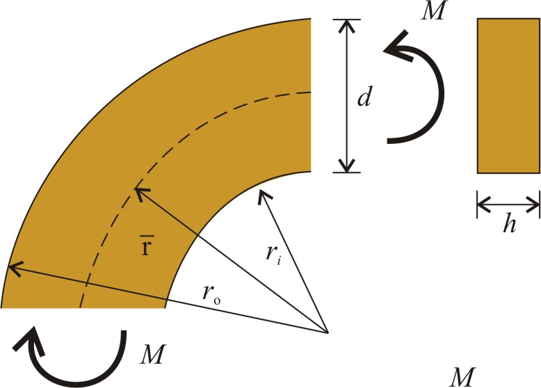
 A rectangular curved beam is subjected to uniform bending moment, M. Height, d and width, h of the cross section are given. Determine and sketch stresses σφ and σr , if
where
a) d = 0.4 m, h = 0.2 m, M = 120 kNm,
b) d = 0.3 m, h = 0.2 m, M = 100 kNm,
c) d = 0.4 m, h = 0.15 m, M = 140 kNm.
Solve Problem
Check the results for the first set of initial data. Problem a) ×106 ×106 ×106 Sketch stresses. Calculate all the other results and compare them to the Table hided below. SolveCompare figure

Check table
Problem a)
2.706×10⁷
2.411×10⁷
2.328×10⁷
-1.93×10⁷
-2.11×10⁷
-2.178×10⁷
2.792×10⁶
1.124×10⁶
5.623×10⁵
Problem b)
4.01×10⁷
3.572×10⁷
3.448×10⁷
-2.86×10⁷
-3.126×10⁷
-3.226×10⁷
4.136×10⁶
1.664×10⁶
8.331×10⁵
Problem c)
4.21×10⁷
3.751×10⁷
3.621×10⁷
-3.003×10⁷
-3.282×10⁷
-3.387×10⁷
4.343×10⁶
1.748×10⁶
8.748×10⁵
Do you need help?
Steps
Solution for the first set of initial data of Problem a) is presented. Step 1. Express the radii of the curvature at the edges of the beam from the initial data. Step 2. Calculate axial stresses, σφ at the edges of the cross section. Step 3. Calculate radial stresses, σr at the middle of the cross section. Step 4. Sketch stresses. Step 5. Calculate all the other results and compare them to the Table hided below. Step by stepCheck curvaturesCheck axial stress
Check radial stress
Compare figure
Check table
Problem a)
27.06
24.11
23.28
-19.30
-21.10
-21.78
2.792
1.124
0.5623
Problem b)
40.10
35.72
34.48
-28.6
-31.26
-32.26
4.136
1.664
0.833
Problem c)
42.10
37.51
36.21
-30.03
-32.82
-33.87
4.343
1.748
0.875
Results
Solution for the first set of initial data of Problem a) is presented. The radii of the curvature at the edges of the beam are expressed from the initial data: Axial stresses, σφ at the edges of the cross section are Radial stresses, σr are All the other results are given in the Table below. Worked out solution
Problem a)
27.06
24.11
23.28
-19.30
-21.10
-21.78
2.792
1.124
0.562
Problem b)
40.10
35.72
34.48
-28.60
-31.26
-32.26
4.136
1.664
0.833
Problem c)
42.10
37.51
36.21
-30.03
-32.82
-33.87
4.343
1.748
0.875