
Apply the strip method to approximate the bending moment diagrams of the rectangular plates given in the Figures below in both directions. All plates are subjected to uniform load: p = 6 kN/m2.
a) Three edges are built-in, the fourth is hinged.
b) All four edges are built-in.
c) Three edges are hinged, the fourth is built-in.


Solve Problem
Problem a) Load in x direction, px [kN/m/m]= Problem b) Load in x direction, px [kN/m/m]= Problem c) Load in x direction, px [kN/m/m]=Solve
Do you need help?
Steps
Problem a) Step 1. Draw the strips, show their supports, write their deflection at the midspan. Step 2. Distribute the load between x and y directions. Determine the load parts from the equality of the strips’ deflections. Step 3. Draw approximate moment diagrams. Problem b) Step 1. Draw the strips, show their supports, write their deflection at the midspan. Step 2. Distribute the load between the x and y directions. Determine the load parts from the equality of the strips’ deflections. Step 3. Draw approximate moment diagrams. Problem c) Step 1. Draw the strips, show their supports, write their deflection at the midspan. Step 2. Distribute the load between x and y directions. Determine the load parts from the equality of the strips’ deflections. Step 3. Draw approximate moment diagrams.Step by step
Load is assumed to be carried by orthogonal strips in x and y directions. The deflections of the strips are identical at the middle of the plate.
Show strips
Show load partsShow moment diagrams
Show strips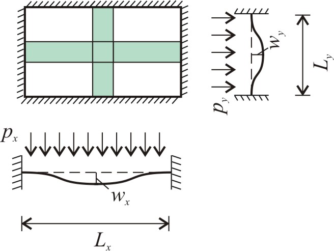
Show load partsShow moment diagrams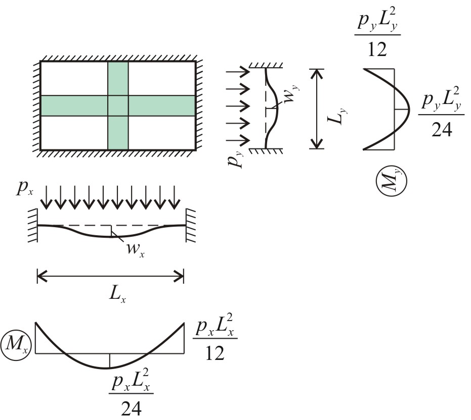
Show strips
Show load partsShow moment diagrams
Results
Problem a) Strips, their supports and their deflections at the midspan are shown in the Figure. The load is distributed between the x and y directions assuming the equality of the strips’ deflections. The approximate moment diagrams are: Problem b) Strips, their supports and their deflections at the midspan are shown in the Figure. The load is distributed between x and y directions assuming the equality of the strips’ deflections. The approximate moment diagrams are: Problem c) Strips, their supports and their deflections at the midspan are shown in the Figure. The load is distributed between x and y directions assuming the equality of the strips’ deflections. The approximate moment diagrams are:Worked out solution
Load is assumed to be carried by orthogonal strips in x and y directions. The deflections of the strips are identical at the middle of the plate.