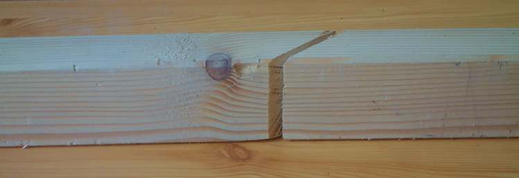
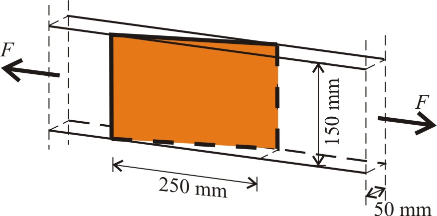
 Scarf joint of a timber element is given in the Figure. Determine the normal and shear stresses in the plane of the glued surface. Give the allowable tensile force, F based on the resistance of the glue, in the plane of the glued surface
a) if the tensile strength of the glue is: 12 N/mm2, and the shear strength is: 5 N/mm2,

b) applying the von Mises yield criterion, the strength of the glue is 12 N/mm2.
Solve Problem
Problem a) Allowable force, F [kN]= Problem b) Allowable force, F [kN]=Solve
Do you need help?
Steps
Step 1. Normal stress arising from the unidirectional tensile force must be transformed to the coordinate system attached to the glued surface. Draw the original x-y and the rotated x’-y’ coordinate systems. Step 2. Calculate the angle of rotation and write the transformation matrix. . Step 3. Write the stress vector in x-y coordinate system in the function of the unknown tensile force. Step 5. Calculate the allowed forces from tension and from shear. Choose the relevant maximum. Step 1. Determine principal stresses. The member is in pure tension stage. Before transformation we had a unidirectional stress, thus . Step 2. Write Von Mises failure criterion and determine the maximum allowed force. Von Mises failure criterion gives the maximum allowed forceStep by stepQuestion a)
Check Figure
Check angleCheck transformation matrix
Check stress vectorStep 4. Perform transformation of stressesCheck transformed stressesCheck allowed force from tensionCheck allowed force from shearCheck maximum allowed forceQuestion b)Check principal stresses
Check maximum allowed force
Results
Normal stress arising from the unidirectional tensile force must be transformed to the coordinate system attached to the glued surface. The transformation of the stresses is the following: where the angle of transformation is . The allowed force from tension is . The allowed force from shear is . The maximum allowed force is the minimum of the above two limits: . The member is in pure tension stage. Before transformation we had a unidirectional stress, thus .Worked out solutionQuestion a)
Question b)
Von Mises failure criterion gives the maximum allowed force